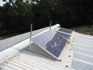
year 5 – New solar system
Attaching the tabbing wire
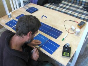
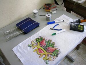
The first step is to solder the tabbing wire onto the backs of all the cells; each cell is 0.5 volts with the backs positive and the fronts negative, so the idea is to wire all forty cells in series which makes a panel with a maximum output of 20 volts and a nominal output of around 16 volts. This output is then feed into the charge controller which adjusts it to suit the battery and load state.
Soldering the cells together
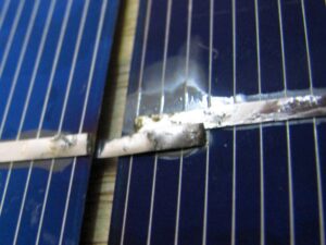
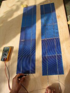
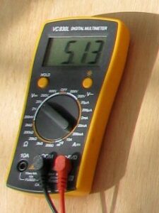
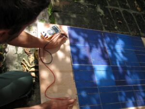
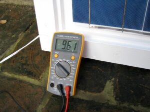
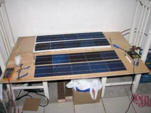
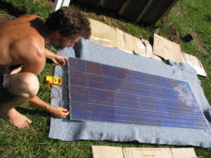
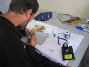
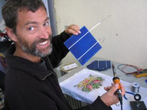
Next I started soldering the cells together into groups of five in series by attaching the tabbing wire that had previously been soldered to the backs to the fronts. One problem that came up with this procedure was that I discovered that I actually have three different types of panels! they’re all the same size, but there’s two slightly different widths between the connection strips, which meant I had to do some dodgy connecting of some of the cells as shown in the second picture below. The final pictures show a voltage measurement on a series of ten cells which is reading correctly at just over 5 volts.
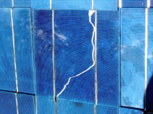
I’ve now got all four rows of five cells soldered together to make the first panel. I temporarily joined them to test the voltage and it’s looking good at 10.59 volts 🙂 The cells are incredibly fragile and I’ve broken some small bits of some and have some cracks in others, it’s like trying to solder together slim potato chips! Not all cells are quite as fragile as this though, one of the three types I’ve got feels a lot sturdier, so I hope that the next set of forty I purchase will all be the same and of the more sturdy type.
Assembling the frames
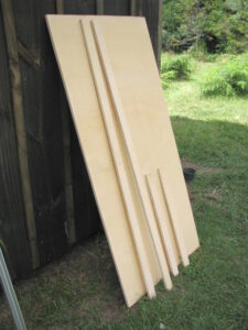
First I got a large sheet of weather-proof ply wood and got it chopped into four equal pieces of 80cm by 120cm which is enough for three panels (I only have enough cells for two panels so far though). Each cell actually only needed to be 80×94 though so these were then cut a bit more.
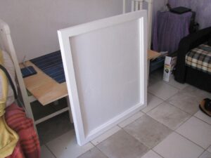
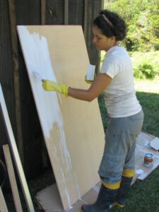
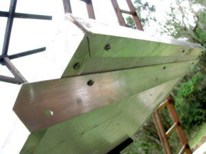
I then cut four long pieces of the ply 6cm wide and another four 5cm wide pieces to form a frame for the glass to sit in. I used a G-clamp to hold the frame pieces in position while drilling the screw holes, and to hold it together tightly while putting each screw in to help ensure that its water-tight, and then Beth put silicone sealant into the remaining cracks before painting it.
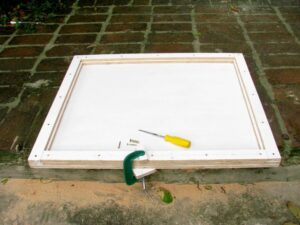
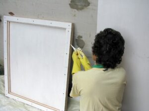
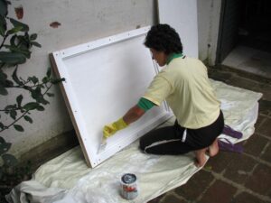
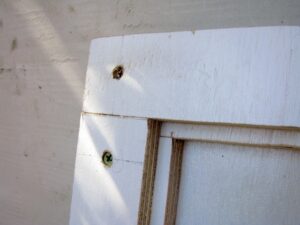
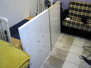
Now that the first frame is painted and dried, we can put some bolts in for mounting the panel securely, put some plastic on to hold the panels away from the bolts and from the wood which can expand and contract a bit with changes in the temperature, and put the power cable through in a secure and water-tight way. I decided to do the first panel completely before doing anything more on the second panel in case I come across problems or find better ways of doing it along the way. For example, I’ve discovered that sealing the cracks with putty would be better than silicone because the silicone won’t allow the paint to stick to it. Also, on the next one I would make the counter-sink holes slightly deeper so that I could putty over all the screws to make them more water-tight and invisible too.
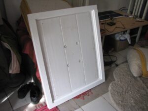
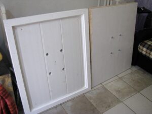
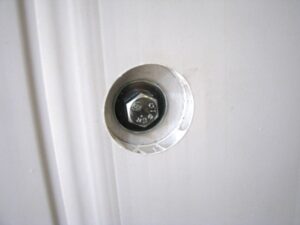
The second frame is now ready for putty and paint. You can see here that I’ve made the counter-sinking a bit deeper. I then drilled four holes into each panel and put sturdy bolts through the so we have a good strong means of mounting them later.
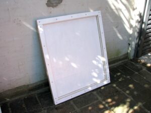
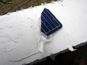
The first panel being all painted and dried was then ready to have some cells put into it 🙂 First I screwed a plastic base onto the frame with holes drilled into it to make way for the bolts. The plastic is to avoid the cells being directly on the wood which may get moisture on it and can bend or expand and contract in differing weather conditions. The plastic was also useful for raising the surface so the cells aren’t in contact with the bolts. Before actually bonding the cells to the plastic, I thought it would be best to test that the silicone we’re using would bind well to them both, so I took a small piece of cell that had broken off one of the corners when I was soldering them together and did a test which showed that the silicone is indeed a good choice 🙂
Installing and wiring the cells
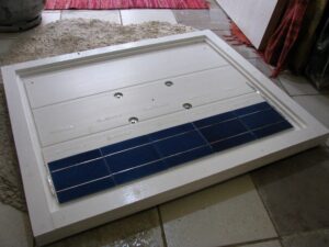
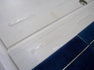
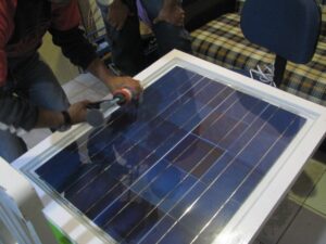
And finally, the process of actually getting the cells into the frame. I first marked with pencil on the plastic a grid so I could position each row of cells accurately, and then put a couple of lines of silicone on the plastic for each of the five cells in a row. I then picked up a row of five that had been soldered together a few weeks ago and carefully placed it in position and slowly moved it in a small circular motion pressing very gently on each cell to get the silicone bonding nicely with both the plastic surface and the cells.
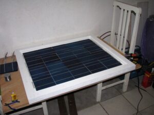
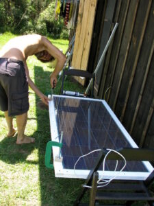
Here’s the first panel all wired up and the voltage tested and showing at a little under 10 volts – which is right for a fairly overcast grey day 🙂
And now the same process for the second panel…
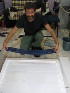
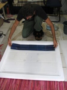
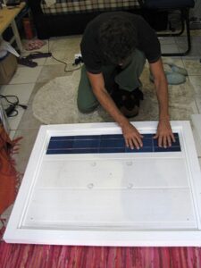
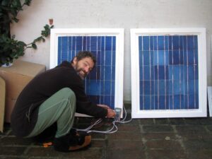
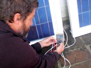
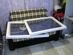
And then we do some final tests to ensure they’re both working correctly before calling the glass guy 🙂 here’s both panels wired together in series with the voltage showing as 17.88 which is very good since they’re in the shade with no direct sun light on them anywhere.
Installing the glass
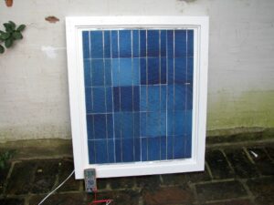
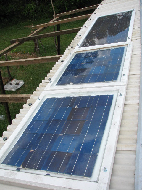
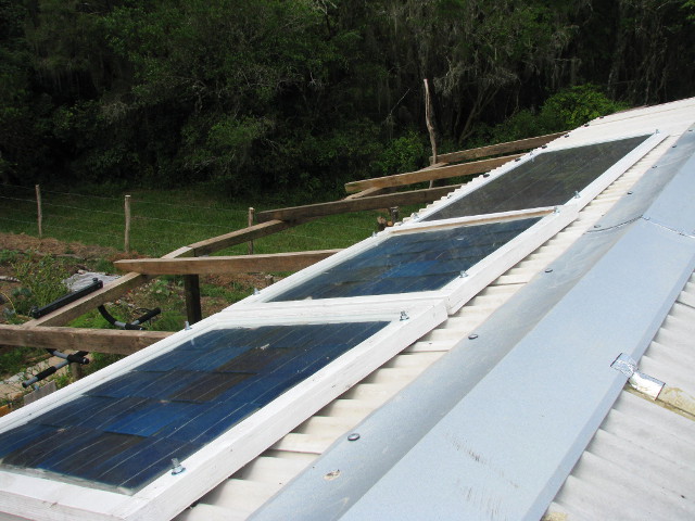
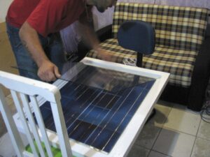
And finally putting the glass in! it only cost an extra R$5 for the glass guys to come over and measure everything and then bring the glass here to us, and then they install it for free so we decided we may as well let them do it 🙂
Design revision (v2)
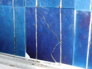
The first panel design has some problems which allowed moisture to accumulate on the inside and also has allowed the cells to bend and crack. They seem to have settled to a final position where no more damage is occurring, but some of them have cracked all the way across, others have just small bits broken off. Amazingly all of this damage has only resulted in about 5% or less reduction in output as we’re getting about 140W from them in full sun.
I ordered another eighty cells from this place which is doing packs of forty for R$289. We actually ordered a pre-built panel for about 2.5 times the cost but it arrived smashed, the guy then sent a replacement panel which also arrived smashed!! so we got him to send two kits of forty cells each instead.
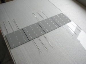
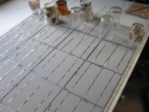
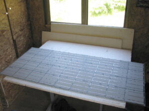
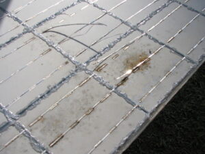
This time I’ve made a slightly different design whereby the tabbing wire is first soldered to the front side of the cells and then the cells are placed face down onto the glass and then glued in place with silicone around the edges of the cells (the pictures show only blobs of silicone in the corners and centres of the sides, but after they were soldered together I put silicone all around the edges).
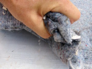
The frame is simpler for this version as there’s no “shelf” that the glass sits upon, instead a soft underlay was placed on the ply panel (a thin sheet of polystyrene or similar could be used, we used a thick compressed-wool blanket) and the glass then sits directly onto this. The soft underlay is so that the glass isn’t directly exposed to vibrations received through the hard wood, and also to distribute uneven pressure caused by the uneven height of the silicone holding the cells to the glass. The glass is then held in place with silicone around the edges, and the power cable goes through a 6mm hole in the ply panel at one end as usual.
In order to ensure that the glass fits very tightly I screwed two adjacent side pieces on first, then positioned the glass (on it’s soft underlay) tight up against those two sides, and then positioned the remaining two sides tightly up against the glass.
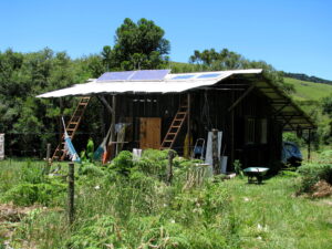
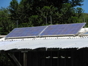
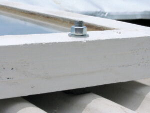
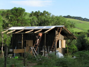
Another simplification is that I’ve dropped the installation bolts from this design, instead I’ve just drilled four holes through the frame and bolted right through rather than having bolts built into the panel structure. Now that we have another panel which is as big as the current two combined and another big one waiting to be assembled, we need to install them in their permanent position on the new north extension roofing panels. I’ve put silicone on the tops of the bolts so that rain can’t enter into the frame and I’ve put a rubber grommet in between the roofing material and the panels to prevent the tightening of the bolts cracking the fragile roofing material.
Another good aspect of version 2 is that it can be disassembled without damaging the cells, which is really important because a few days ago it started having problems with the current not adding to the output of the other panels properly. I could see that there was some moisture between the glass and some of the cells so the panel wasn’t water-tight, and after I took it down and disassembled it I found that the blanket that the glass lays on to distribute the pressure of the uneven surface on the back of the cells was completely soaked and had caused the tabbing wire to disconnect from the back of many cells, and was also causing a partial short-circuit.
Another design revision (v3)
The version 2 panel has been running for a few months now and a few problems have begun to show up. Firstly the wood sides are a problem, they bend and the paint comes off allowing water to enter. Secondly I should have used something for the soft underlay that the glass sits on that’s doesn’t absorb water like polystyrene or a form mat, because the water that has entered won’t exit, it just sits in the blanket probably draining a portion of the energy from the cells since it’s in contact with the tabbing wire on the back of them.
One aspect of the version 2 design are successful though, which is the method of attaching the cells directly to the back of the glass with silicone and support it with a soft underlay. There’s not the slightest hint of change in the cells themselves – although they haven’t been through the test of snow yet, but it’s certainly a much better method than version 1.
Version 3 is new design which is similar to version 2 but using a bubble-wrap backing to support the glass and using L-section aluminium for the sides. I can’t do a design like the professional ones that smashed because they require specialised aluminium framing, rubber sealing to match and some specialised adhesive to attach the cells with. I want to come up with a design that’s durable but also made with minimal work and completely with materials that are readily available at any small town hardware store.
After the version 2 panel started having problems due to moisture, I took it down and upgraded it to our first version 3 design. There’s a couple of slight problems with this design that I’ll need to iron out when I assemble the next one which is almost ready. The first issue is that either we need to get slightly thinner ply for the backing, or find some different L-aluminium that has at least one of the sides a little longer. But I’ve assembled it anyway and just used more silicon to ensure it’s sealed ok.
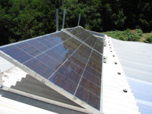
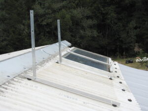
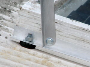
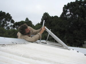
I’ve also improved the way the v3 panel is installed so that we can adjust the angle for summer or winter – mainly winter as we need to have optimal sun on the overcast winter days when the sun is low in the sky.
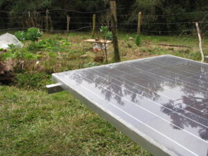
Finally months later the second v3 panel was completed and installed.
